Introduction
Ballast has been identified as the main cause of average and differential settlement
of railway track with passage of traffic. This is also influenced by the inherently
variable nature of the formation but if the formation is adequately specified
ballast remains the main cause of loss of geometry of track and subsequent loss
in ride quality of the track (Selig and Waters 1994). For high speed trains
the passenger is more sensitive to ride quality deterioration, thus track monitoring
and maintenance is more frequently required. It is generally accepted that the
cost of maintaining a railway track is several times greater than that of an
equivalent length of road lane.
Ballast
Ballast provides resiliency to the track and distributes stresses from the sleepers
to the subgrade. Ballast was not given due consideration in the initial years
of railway construction and any cheaply and easily available material like ashes,
chalk and clay were used as ballast. It was not until 1890’s that engineers
realized the importance of using good quality stone as ballast, although the
specification for the stone was not very clear about the size and quality. There
is mention of an instance, by F.R. Conder in his book ‘The men who built
the railways’ (1983, first published in 1868), where specification for
ballast stated that no bit of broken stone be used as ballast larger than a
man could put in his mouth. Even as late as 1922, 90% of the former North Eastern
Railway was ballasted with ash (Cope 1993). The current practice is to use uniformly
graded ballast but use of well graded ballast has been suggested, with smaller
sizes to reduce contact forces (Selig 1984, Leeves CG 1982). At present no universal
agreement exists concerning the specifications for the ballast material index
characteristics and it is a subject still being researched.
Track Geometry and maintenance
Measured Shovel packing - The traditional method of track maintenance was manual
packing of ballast under the sleepers which involved packing 5-10 mm stone chippings
below the sleepers to bring them up to level.. A gang of maintenance workers
would move along the track and measure the amount of slack in a track section
using a set of sighting boards, next they would strike the sleepers with a hammer
to check for voided sleepers. Void meters were used to determine the amount
of stone chippings needed to fill up the void and this was added to the stone
chippings required for removing the slack in the track. The portion of track
was lifted up using jacks and stones chips filled in under the sleepers approximately
400mm either side of the rail. It is claimed that vertical alignment could be
corrected to an accuracy of a few millimeters using MSP. But the traditional,
manual track improvement measures have become economically obsolete. Railways
with heavy traffic, welded rails and concrete sleepers require mechanization
of track maintenance to maintain minimum safety levels (Anderson and Mundrey
1995).
The most widely used machines for track maintenance are tampers and stoneblower.
Tamping machines squeeze the ballast up below the sleepers after the sleepers
are raised to the desired level while stone blowing machines add stone to the
existing ballast surface after lifting the sleeper up to the required level.
Thus tampers disturb the compacted ballast beneath the sleepers
and vertical track geometry deteriorates rapidly after tamping. The resultant
track profile after tamping rapidly assumes its original pre-tamp condition,
a phenomenon known as ballast memory. An explanation of this phenomenon is given
by Selig & Waters (1994). It has been observed that for low tamping lifts
the ballast below the sleepers is squeezed upwards and dilates into the void
between the sleeper and the ballast surface. As the lift is small, on contacting
the underside of the sleeper further deformation of ballast cannot take place
and thus arrangement of ballast particles within the ballast is unchanged. The
passage of traffic re-compacts the ballast and the particles adopt their original
position with respect to each other and the track assumes it original pretamp
shape. A solution to this problem as suggested by Selig and Waters is high lift
tamping. In high lift tamping the ballast will have sufficient room for maximum
ballast dilation and rearrangement of particles will take place with new particles
being absorbed into the skeleton. Re-compaction of this new ballast skeleton
by traffic will introduce a new geometry to the track. This method is also used
for improving inherent quality of track. Limited head room and shortage of crib
ballast may inhibit use of high lift tamping process. Another disadvantage of
tamping process is that it crushes ballast particles and generates stone dust
which increases ballast fouling.
Stone blowing machines cause minimal disturbance of ballast below the sleeper
and thus result in far greater durability of top ballast and generate less dirt.
Stone blowing machines use a stone size of 20mm for their operations. Over a
period of time stone blowing operations create a layer of 20mm stone on top
of the 50mm standard railway ballast. Research by Anderson et al (1998) on this
two layered ballast formation has not shown any deleterious effects on overall
track response. The drawback of a stoneblower is that rectification of long
wavelength vertical defects with a stone blower would require impractical quantities
of stone chippings and the maximum amount of track lift that can be achieved
by a stone blower is 40mm.
After stoneblowing the track-life before the next maintenance
is on average four times longer than track maintained by traditional tamping
methods. In addition a tamper generates around 4kg of fines per sleeper for
one tamping insertion while only 0.5 kg of fines per sleeper are produced by
an equivalent stoneblowing cycle. Tamping is less effective on fouled ballast
while stoneblowing can work effectively on track with fouled ballast. A track
with a stable compacted bed even though it is fouled can be maintained by the
stoneblower (Selig 1994). Thus stone blowing prolongs the track life and postpones
replacement of ballast.
Tests on two layered ballast system
Laboratory testing involved tenth scale model tests, full scale box test and full scale single sleeper tests. A cyclic loading was used to simulate the passing of axles over the sleepers and the tests consisted of simple cycles and uplift cycles. In simple cycles sleepers were loaded with a cyclic load for 20 cycles and the maximum displacement for each cycle recorded, this represented a track with no voided sleepers. In uplift cycles the sleepers were lifted up to simulate formation of void below the track, the amount of uplift for the tests described below was 2.5 mm for 10th scale model tests and 25mm for full scale tests, i.e. a void size of 25mm full scale. Again for the uplift cycles the maximum displacement for each cycle was measured.
Model tests - A ten sleeper assembly of tenth scale model sleepers made of wood
was used for the model tests. The ballast below the sleepers was modeled as
5mm stone (Tenth scale of British Railway ballast specification) and the crib
ballast was modeled as 2mm stone (Tenth scale of Stone blowing stone specification).
The photograph shows the tenth scale model sleeper assembly.
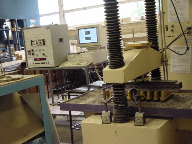
The sleeper assembly was attached to a cyclic loading machine with the help of a rigid beam. Both 5mm stone and 2mm stone were used as crib ballast to get a comparision of the proposed system with the current British Railway practice The process was computer controlled thus many types of cycles could be run on the model. 20 simple cycles and 20 uplift cycles were run on the model.
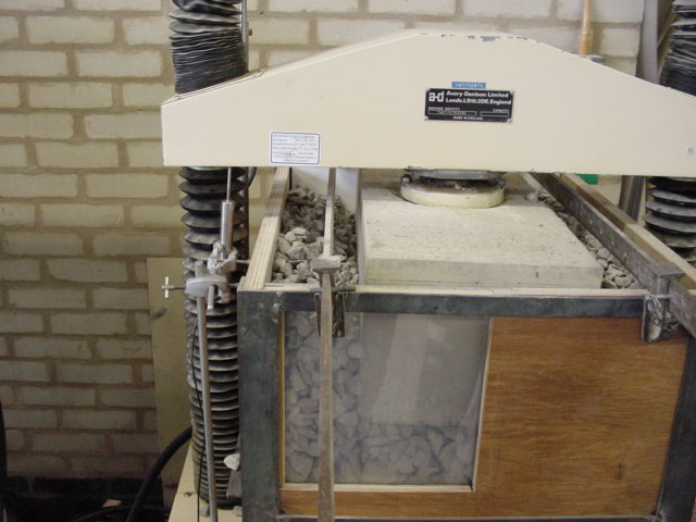 Box
test - A reinforced concrete sleeper pad was used for the box tests. Boundary
conditions of live track were created in a box reinforced by steel frame as
shown in figure. The tests were computer controlled using labview and 20 simple
cycles and 20 uplift cycles were run with both 50mm and 20mm as crib ballast.
The inspection window was used to study movement crib ballast during the uplift
cycles.
Box
test - A reinforced concrete sleeper pad was used for the box tests. Boundary
conditions of live track were created in a box reinforced by steel frame as
shown in figure. The tests were computer controlled using labview and 20 simple
cycles and 20 uplift cycles were run with both 50mm and 20mm as crib ballast.
The inspection window was used to study movement crib ballast during the uplift
cycles.
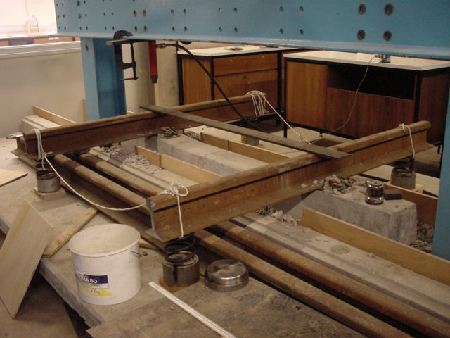
Full scale single sleeper test - Boundary conditions of live railway track were created in the laboratory using two rigid concrete panels erected on both sides of a single concrete sleeper as shown in figure. Loading was applied by two hydraulic rams onto the rails and displacement of the sleeper into the ballast was monitored by using two Linear voltage displacement transducers and the data was logged into a data logger. 20 simple cycles and 20 uplift cycles were run.
Results were plotted as maximum displacement of sleeper against cycle number.